Generator and Motor
A hand-cranked generator can be used to generate voltage to turn a motor. This is an example of energy conversion from mechanical to electrical energy and then back to mechanical energy.

As the motor is turning, it also acts as a generator and generates a "back emf". ByLenz's law, the emf generated by the motor coil will oppose the change that created it. If the motor is not driving a load, then the generated back emf will almost balance the input voltage and very little current will flow in the coil of the motor. But if the motor is driving a heavy load, the back emf will be less and more current will flow in the motor coil and that electric power being used is converted to the mechanical power to drive the load.
AC MOTORS AND GENERATORS
DC MOTORS AND GENERATORS
_________
How Does an Electric Motor Work?

AC Motors
AC Motor
 | As in the DC motor case, a current is passed through the coil, generating a torque on the coil. Since the current is alternating, the motor will run smoothly only at the frequency of the sine wave. It is called a synchronous motor. More common is the induction motor, where electric current is induced in the rotating coils rather than supplied to them directly. |
DC Motor
DC Motor Operation

Current in DC Motor

Magnetic Field in DC Motor

Force in DC Motor

Torque in DC Motor

________________
How Does an Electric Generator Work?

AC Generator
AC Generator
The turning of a coil in a magnetic field produces motional emfs in both sides of the coil which add. Since the component of the velocity perpendicular to the magnetic field changes sinusoidally with the rotation, the generated voltage is sinusoidal or AC. This process can be described in terms of Faraday's law when you see that the rotation of the coil continually changes the magnetic flux through the coil and therefore generates a voltage.
DC Generator
Motors & Generators.
These videos explains the key concepts in motors and generators including motor effect, ac/dc motors, slip / split ring commutators, faradays law of induction, lenz law, eddy current and back emf
Schematics & Operation of Different Types of Motor
| The schematics shown here are idealised, to make the principles obvious. For example, this animation has just one loop of wire, no bearings and a very simple geometry. Real motors use the same principles, but their geometry is usually complicated. |
DC motors
A simple DC motor has a coil of wire that can rotate in a magnetic field. The current in the coil is supplied via two brushes that make moving contact with a split ring. The coil lies in a steady magnetic field. The forces exerted on the current-carrying wires create a torque on the coil.
- * A number of different nmemonics are used to remember the direction of the force. Some use the right hand, some the left. For students who know vector multiplication, it is easy to use the Lorentz force directly: F = q v X B , whence F = i dL X B . That is the origin of the diagram shown here.
The torque generated over a cycle varies with the vertical separation of the two forces. It therefore depends on the sine of the angle between the axis of the coil and field. However, because of the split ring, it is always in the same sense. The animation below shows its variation in time, and you can stop it at any stage and check the direction by applying the right hand rule.
Motors and generators
Now a DC motor is also a DC generator. Have a look at the next animation. The coil, split ring, brushes and magnet are exactly the same hardware as the motor above, but the coil is being turned, which generates an emf.- emf = − dφ/dt = − (d/dt) (NBA cos θ) = NBA sin θ (dθ/dt) = NBAω sin ωt.
An alternator
If we want AC, we don't need recification, so we don't need split rings. (This is good news, because the split rings cause sparks, ozone, radio interference and extra wear. If you want DC, it is often better to use an alternator and rectify with diodes.) In the next animation, the two brushes contact two continuous rings, so the two external terminals are always connected to the same ends of the coil. The result is the unrectified, sinusoidal emf given by NBAω sin ωt, which is shown in the next animation.Back emf
Now, as the first two animations show, DC motors and generators may be the same thing. For example, the motors of trains become generators when the train is slowing down: they convert kinetic energy into electrical energy and put power back into the grid. Recently, a few manufacturers have begun making motor cars rationally. In such cars, the electric motors used to drive the car are also used to charge the batteries when the car is stopped - it is called regenerative braking. So here is an interesting corollary. Every motor is a generator. This is true, in a sense, even when it functions as a motor. The emf that a motor generates is called the back emf. The back emf increases with the speed, because of Faraday's law. So, if the motor has no load, it turns very quickly and speeds up until the back emf, plus the voltage drop due to losses, equal the supply voltage. The back emf can be thought of as a 'regulator': it stops the motor turning infinitely quickly (thereby saving physicists some embarrassment). When the motor is loaded, then the phase of the voltage becomes closer to that of the current (it starts to look resistive) and this apparent resistance gives a voltage. So the back emf required is smaller, and the motor turns more slowly.Coils usually have cores
In practice, (and unlike the diagrams we have drawn), generators and DC motors often have a high permeability core inside the coil, so that large magnetic fields are produced by modest currents. This is shown at left in the figure below in which the stators (the magnets which are stat-ionary) are permanent magnets.

'Universal' motors
The stator magnets, too, could be made as electromagnets, as is shown above at right. The two stators are wound in the same direction so as to give a field in the same direction and the rotor has a field which reverses twice per cycle because it is connected to brushes, which are omitted here. One advantage of having wound stators in a motor is that one can make a motor that runs on AC or DC, a so called universal motor. When you drive such a motor with AC, the current in the coil changes twice in each cycle (in addition to changes from the brushes), but the polarity of the stators changes at the same time, so these changes cancel out.AC motors
With AC currents, we can reverse field directions without having to use brushes. This is good news, because we can avoid the arcing, the ozone production and the ohmic loss of energy that brushes can entail. Further, because brushes make contact between moving surfaces, they wear out. The first thing to do in an AC motor is to create a rotating field. 'Ordinary' AC from a 2 or 3 pin socket is single phase AC--it has a single sinusoidal potential difference generated between only two wires--the active and neutral. (Note that the Earth wire doesn't carry a current except in the event of electrical faults.) With single phase AC, one can produce a rotating field by generating two currents that are out of phase using for example a capacitor. In the example shown, the two currents are 90° out of phase, so the vertical component of the magnetic field is sinusoidal, while the horizontal is cosusoidal, as shown. This gives a field rotating counterclockwise.If we put a permanent magnet in this area of rotating field, or if we put in a coil whose current always runs in the same direction, then this becomes a synchronous motor. Under a wide range of conditions, the motor will turn at the speed of the magnetic field. If we have a lot of stators, instead of just the two pairs shown here, then we could consider it as a stepper motor: each pulse moves the rotor on to the next pair of actuated poles. Please remember my warning about the idealised geometry: real stepper motors have dozens of poles and quite complicated geometries!
Induction motors
Now, since we have a time varying magnetic field, we can use the induced emf in a coil – or even just the eddy currents in a conductor – to make the rotor a magnet. That's right, once you have a rotating magnetic field, you can just put in a conductor and it turns. This gives several of the advantages of induction motors: no brushes or commutator means easier manufacture, no wear, no sparks, no ozone production and none of the energy loss associated with them. Below left is a schematic of an induction motor.This schematic suggests why they might be called squirrel cage motors. The problem with the induction and squirrel cage motors shown in this animation is that capacitors of high value and high voltage rating are expensive. One solution is the 'shaded pole' motor, but its rotating field has some directions where the torque is small, and it has a tendency to run backwards under some conditions. The neatest way to avoid this is to use multiple phase motors.
Three phase AC induction motors
Single phase is used in domestic applications for low power applications but it has some drawbacks. One is that it turns off 100 times per second (you don't notice that the fluorescent lights flicker at this speed because your eyes are too slow: even 25 pictures per second on the TV is fast enough to give the illusion of continuous motion.) The second is that it makes it awkward to produce rotating magnetic fields. For this reason, some high power (several kW) domestic devices may require three phase installation. Industrial applications use three phase extensively, and the three phase induction motor is a standard workhorse for high power applications. The three wires (not counting earth) carry three possible potential differences which are out of phase with each other by 120°, as shown in the animation below. Thus three stators give a smoothly rotating field.Linear motors
A set of coils can be used to create a magnetic field that translates, rather than rotates. The pair of coils in the animation below are pulsed on, from left to right, so the region of magnetic field moves from left to right. A permanent or electromagnet will tend to follow the field. So would a simple slab of conducting material, because the eddy currents induced in it (not shown) comprise an electromagnet. Alternatively, we could say that, from Faraday's law, an emf in the metal slab is always induced so as to oppose any change in magnetic flux, and the forces on the currents driven by this emf keep the flux in the slab nearly constant.Homopolar Motors
 Because there is always a current path between the brushes (or at least there would be if they were ideal), the resultant torque is steady. Note that (in this version) there is only one current-carrying path, compared with many in a typical multipolar motor. On the other hand, the current could be large if the brushes had low resistance. | |
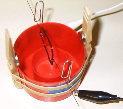
In a simple design for a very simple homopolar motor, the magnet itself (or its coating) touches the cell and is used as the contact for the brushes. In this design, the rotor is not a disk, but just a piece of wire with two current carrying paths (for balance). The piece of wire includes all three brushes. It uses a 1.5 V cell, one of whose terminals is the contact for one brush (the middle point on the wire), and a cylindrical rare earth magnet, whose circumference is the contact for the other two.  | Safety warning: Because the battery is short-circuited by a piece of copper wire, this motor should only be run for very short times: it not only uses the battery very quickly, but also could heat it up, which is a potential safety hazard. |
Homopolar Generators
In the simple schematics below, we've made a homopolar generator by replacing the cell that drove the homopolar motor with a voltmeter. Whereas the homopolar motor converts electrical energy (supplied by the cell) into mechanical energy, the homopolar generator does the reverse: we provide mechanical energy to turn the disk and obtain an emf and (if a current path exists) an electric current. Again, a homopolar generator is conceptually a little simpler than its multipole cousins but, because there is only one current path, the emf is small. (On the other hand, ideal brushes would in principle allow a large current.) | In our generator (above), one handle (left) turns the rotor and another (right) turns the magnet, which is the black block in the middle, just to the right of the two blue wires. The axis of rotation is horizontal, whereas that in the animation is vertical. The multimeter is reading mV DC. | |
Variations on homopolar generators
| Think carefully about these questions before you answer and before you look at the film clips below. In science, the authoritative answer is always obtained by asking the universe – i.e. we do the experiment. So the film clips below show the interesting configurations: both rotor and magnet rotating, and magnet rotating but rotor not rotating. | |
Some notes about AC and DC motors for high power applications
AC motors are used for high power applications whenever it is possible. Three phase AC induction motors are widely used for high power applications, including heavy industry. However, such motors are unsuitable if multiphase is unavailable, or difficult to deliver. Electric trains are an example: it is easier to build power lines and pantographs if one only needs one active conductor, so this usually carries DC, and many train motors are DC. However, because of the disadvantages of DC for high power, more modern trains convert the DC into AC and then run three phase motors.Power tools and some appliances use brushed AC motors. Brushes introduce losses (plus arcing and ozone production). The stator polarities are reversed 100 times a second. Even if the core material is chosen to minimise hysteresis losses ('iron losses'), this contributes to inefficiency, and to the possibility of overheating. These motors may be called 'universal' motors because they can operate on DC. This solution is cheap, but crude and inefficient. For relatively low power applications like power tools, the inefficiency is usually not economically important.
If only single phase AC is available, one may rectify the AC and use a DC motor. High current rectifiers used to be expensive, but are becoming less expensive and more widely used.